This is part #5 of my adventures in Building the Internet of Things with the Raspberry Pi with @sn0wcat. This post continues Getting started with Raspberry Pi 3 and my first Hello Blinky 1.0 with the Raspberry Pi 3 and shows our learning process with a new technology. You can also read about Setting up Raspbian on the Raspberry Pi 3.
The project
We want to extend Hello Blinky 1.0 project with a website:
- we enter a message,
- this message is sent to Azure and queued,
- the Raspberry Pi pulls a message from the queue,
- Optional: the buzzer on the Raspberry Pi goes off for the incoming message,
- the Raspberry Pi displays the message on a screen,
- the LED blinks it in Morse code,
- Optional: we push the button on the Raspberry Pi to acknowledge the message,
- Azure gets the notification of the acknowledgement,
- the website is updated.
What I learned
- How to connect the Raspberry Pi to a LED and a LCD screen
- How to programmatically write to the LCD screen connected to the Raspberry Pi
- How to create a Windows IoT background application
- How to create ServiceBus queues on Azure
- How to send to and receive messages from queues
- How to create web jobs
- How to create RESTful API with Swagger
- How to create websites with Bootstrap, Angular and TypeScript
Hardware setup
All the components we use for this project are in the Sunfounder Project Super Starter Kit for Raspberry Pi (Except the Pi, of course :)). We connect all the components as described booklet that comes with the kit.
Main components:
- Raspberry Pi 3 with Windows I0T Core
- Breadboard
- GPIO extension board
- GPIO cable
We use the 40-pin GPIO extension board and GPIO cable to connect the breadboard to the Raspberry Pi 3.
For the LED:
- 1 LED
- 1 resistor
- Jumper wires
We connect the LED to the breadboard on GPO 5 and temporarily connect the wire from the pin to the ground to check if it all works.
For the screen:
- 1 LCD
- 1 Pin header
- 1 Potentiometer
- Jump wires
We connect the LCD to the ground, power supply, enable pin, register select and the data input and output with 4-bit operation mode. We will need this configuration for our implementation later.
Screen input pins:
D7 => GPO 18
D6 => GPO 23
D5 => GPO 24
D4 => GPO 25
Enable pin:
E => GPO 22
Register selection:
RS => GPO 27
Try no. 1
We have a tiny wiring problem and we use these lessons to correct the wiring:
Try no. 2: We’re tinkering with the wires some more.
Try no. 3: The LCD is not stable so we adjust the hardware again.
For the buzzer:
- 1 Buzzer
- 1 PNP transistor
- 1 resistor
- Jumper wires
For the button:
- 1 button
- Jumper wires
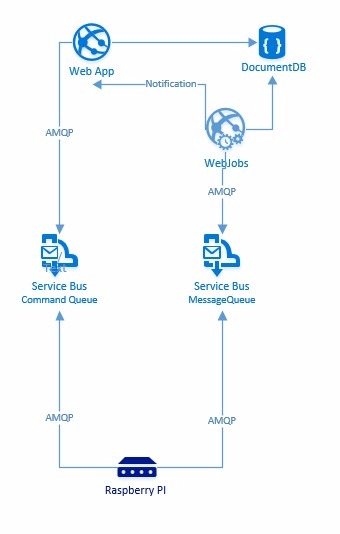
The architecture
Add code
Development environment
Same as for Hello Blinky 1.0, I am using the Visual Studio 2015 Community Edition and Visual Studio Code. I store this project in the cloud on the Visual Studio Team Services. My goal is to use free tools for this project.
I install the updates in Visual Studio 2015:
- Microsoft ASP.NET Web tools
- Microsoft SQL Server Update for database tools
- Microsoft Azure SDK
First we will migrate parts of our Hello Blinky 1.0 project into a new headless project.
The Hello Blinky 1.0 is a headed XAML application and we want to use a background application this time.
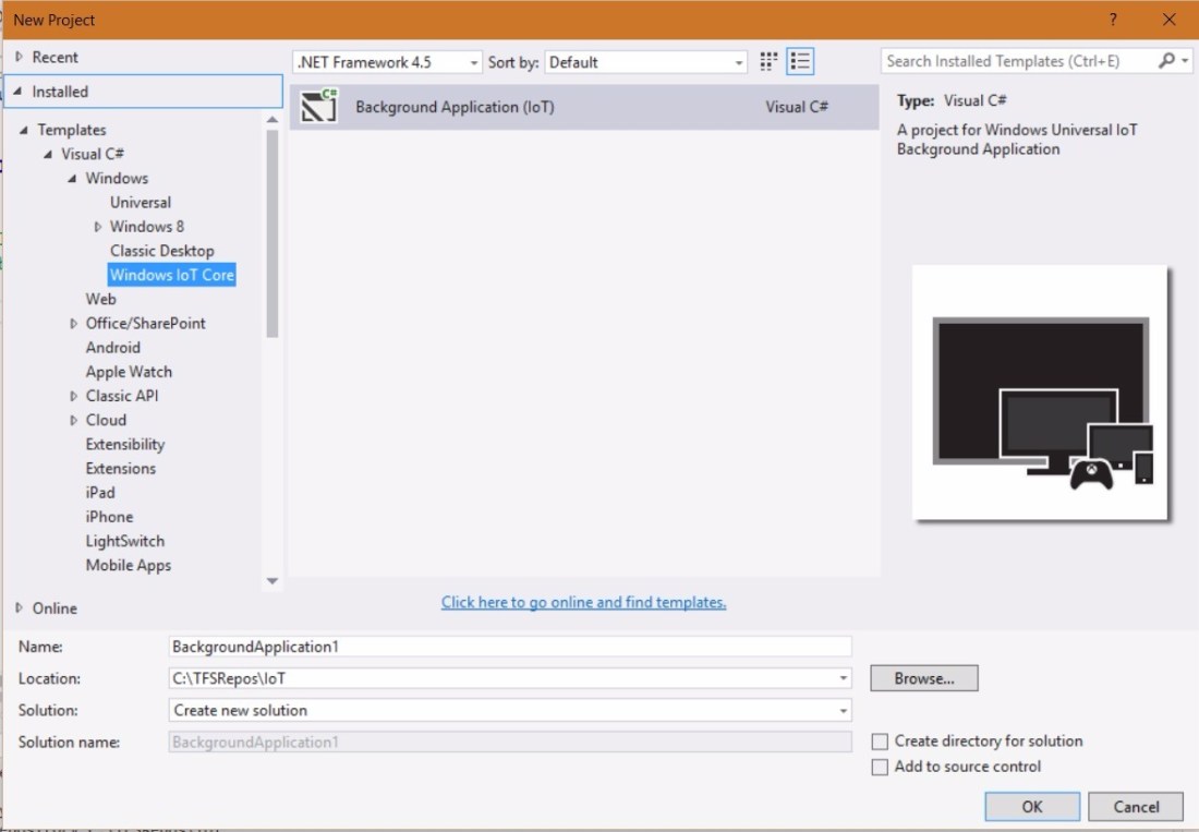
We create a new blank solution in Visual Studio 2015 and add it to source code. We create a new headless project with the Windows IoT Core Project Template in the solution which is going to do the operations on the Raspberry Pi. You can install the template from here if you don’t have it already.
We add a reference to Windows IoT Extensions for the UWP in our project to have the GPIO.

We add the publisher display name in the appmanifest.
We move our implementation for Morse code to this new: we will need MorseLights.cs and MorseConverter.cs. We have to make MorseLights class sealed because WinRT types have to be sealed. [Why?] Now we test if the LED blinks in Morse code by calling our MorseLights class’ Blink method from the asynchronous Run method in our StartupTask class.
Next we are going to try to write a hard-coded text to the LCD screen connected to the Raspberry Pi.
We take a look at the sample in C and Python to see how to write to the screen. The Starter Kit does not contain the implementation for C# and the Microsoft IoT samples contain the implementation for 1306 but not for our LCD1602. So we are going to write it ourselves using both the Python code and the 1306 sample as inspiration and then we test if the text is displayed on the screen by calling our LCDDisplay class’ SendMessage method from the asynchronous Run method in our StartupTask class. Finally we clean up the LcdDisplay class that holds the implementation for writing to the screen.
Setting up the cloud infrastructure
Next up we’re going to create the queues for handling the incoming and outgoing messages.
We install Service Bus Explorer 2.6 so we are able to watch the messages coming in and out of the queue. I cannot install it with the package manager Chocolatey because this package was rejected and I can’t find it in the MSDN Code Library but I will get it directly from GitHub.
We go to the Azure Portal and do the following:
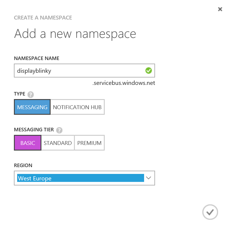
We create the service bus namespace for input and output message queues
Type Notification Hub is better for IoT projects but we will use Messaging because we don’t expect having to scale out this application. 🙂
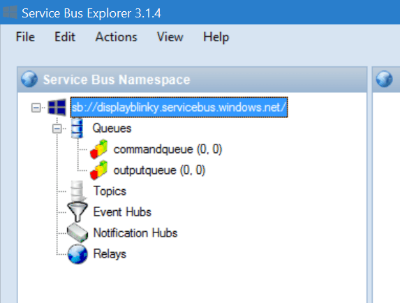
 We create two queues for input and output messages
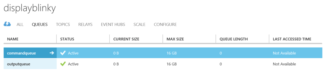
Command queue


Output queue


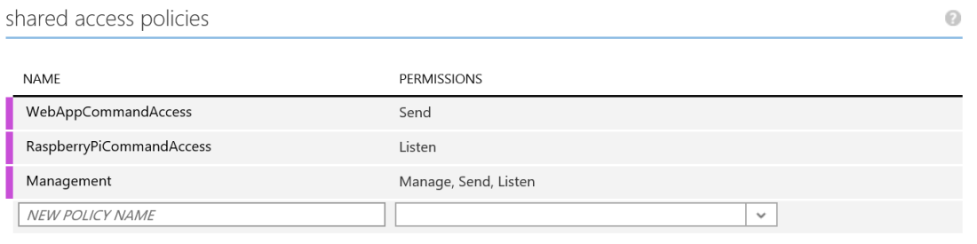
Next up we configure the access policies for the queues.
Command queue
The web app can send commands to the queue and the Raspberry Pi listens to the commands in the queue.
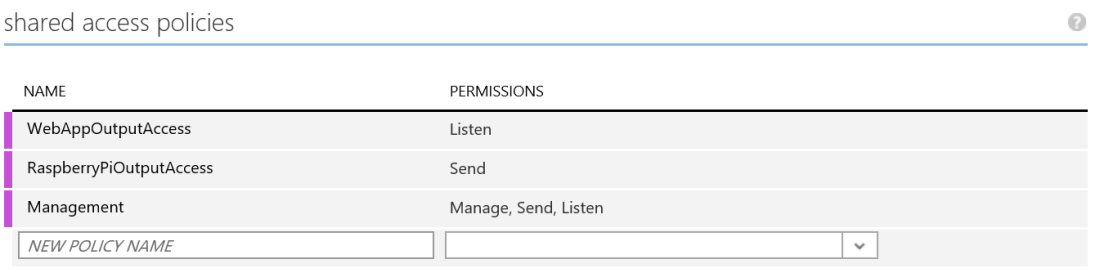
Output queue
The Raspberry Pi can send feedback to the queue and the web job listens to the queue and notifies the web app.
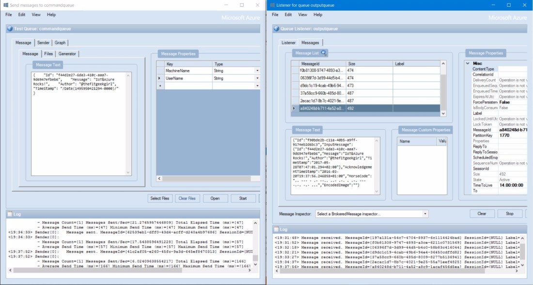
Next we check the queue in the Service Bus Explorer.
We copy the access connection string for the management key of the namespace from the portal and enter it to connect to the service bus namespace.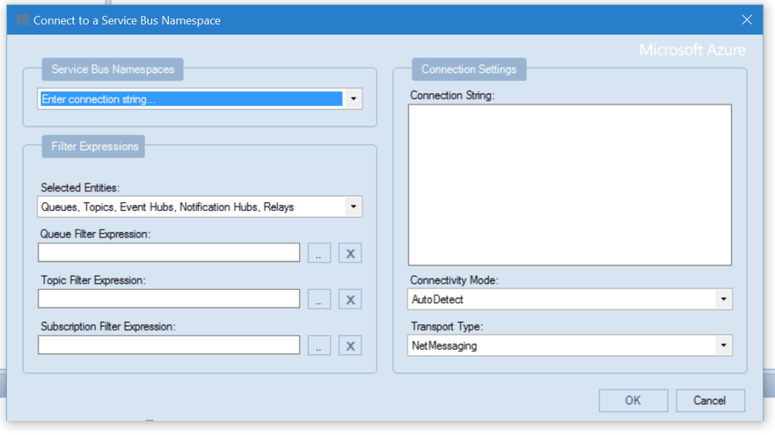
We test that we can send and receive messages in the output queue.
We create queue listener and listen to the messages.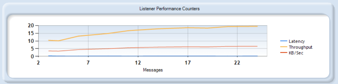
We’re going to use JSON for the messages so we can easily display it in the website and also store it in DocumentDB.
Create the DocumentDB instance in the Azure Portal


Connecting the code to the cloud infrastructure
First we create a new project for the common classes that we will reuse from the Raspberry Pi and the web app projects. We create a class for the input message and a class for the response message. We reference this new project in the Raspberry Pi project and use these new classes for the input and output messages: temporarily just to test that it works, we send hard-coded input message programmatically to the Pi and display it on the screen.
We use the message queues in the Raspberry Pi project
Next step is to swap this hard-coded input message that we send from the code to using the CommandQueue that we set up in the cloud. We will use the Service Bus Explorer to send the messages to the queue for now, these will be queued, received on the Pi and displayed on the screen. The Service Bus portal page has a great collection of resources about tools and How To articles and the Start using queues with .Net leads us to this article.
We need the Service Bus package for IoT Core so we install Microsoft IoT Connections for Azure in the project for the Raspberry Pi.
We create a Client QueueClient from connection string with the connection information RaspberryPiCommandAccess that was configured to listen to the queue and a Sender QueueClient with the connection information RaspberryPiOutputAccess that we configured to send messages. The Client receives the message from the command queue, remove the message from the queue with Complete(), the message is sent to the LCD and the Sender sends back an acknowledgement message to the output queue.
We simulate the Raspberry Pi with a WebJob
How to use Azure Service Bus with the WebJobs SDK
We write a simulation web job which will read from and write to the queue so that we can simulate the Raspberry Pi response and work on the site without using the Pi. We create a web job with the Azure WebJob project template for C# called DisplayPi.SimulationJob. Every job writes data to a log storage, for this we have to set up the connection to the storage. We create a new storage account in the Portal, if it doesn’t exist yet, and we add the connection string in the App.config: AzureWebJobsDashboard and AzureWebJobsStorage.
We add two new packages from Nuget to the SimulationJob project: WindowsAzure.ServiceBus and Microsoft.Azure.WebJobs.ServiceBus.
Unfortunately we can’t reference our Interfaces project in the SimulationJob project because it’s Universal Windows project so we create a portable class library DisplayPi.Common. We move our Interfaces and Helpers to the new project and we reference this new project in our SimulationJob and our DisplayPi projects.
The job has to be configured to use service bus in the Main() method of the Program class.
We create a method ProcessQueueMessage() in our Functions class inside our SimulationJob project that is triggered when a new message is written in the CommandQueue, this will act like the Raspberry Pi and send an acknowledge message to the OutputQueue for each incoming message in the CommandQueue.
We create a second web job to store the output messages in DocumentDB
We create a new web job called DisplayPi.DocumentWriter, reference the same assemblies, add connection strings as before and reference DocumentDB client, Microsoft Azure.DocumentDB.
We use this NoSQL tutorial: Build a DocumentDB C# console application to programmatically create our DisplayPiDB database and create a document collection for the messages DisplayPiResponseMessages in the Main() method of the Program class. Finally we write the messages from the OutputQueue to the database in the ProcessQueueMessage() method in our Functions class by creating a document for the message in the document collection. We install Azure DocumentDB Studio to test that the messages are stored in the database but this can be done in Visual Studio directly in the Cloud Explorer as well.
We build a website to write in the command queue and read from the output queue
First we install:
- Web Essentials for Visual Studio 2015.
- Node.js Tools 1.1 for Visual Studio 2015
We make a RESTful API using Swagger with two operations: sending and receiving messages. We make the API Design First Workflow with the Swagger Editor. You can check our API here in Swagger UI. We can generate the server and the client in the language that we prefer. We choose Node.js for server and TypeScript Angular for client.
The Node.js server includes the YAML file with the REST API definition, a README.md and the API implementation. We install the dependencies that we need for the Node.js server. We add the dependency to Azure and install the package as described in the section “Create a Node.js application” in this article. We add the dependency and install the node-uuid package for Guids.
We instantiate a service bus service with azure.createServiceBusService. We then extend the implementation of sendMessage by creating a new brokered message. Keep in mind that we had to JSON.stringify the body for this to work, we lost an hour trying to figure this out and the error message was not helpful. Finally we sendQueueMessage using the service bus service to our commandQueue.
Next we have to implement the getMessages to return the top 10 messages that we acknoledged and sent to our DocumentDB. We add the dependency to documentdb and isntall the package. We use the method from step 4 in this article to query the database. We basically instantiate the DocumentDB client, create the query and run a select with queryDocuments on the client.
We did this in Visual Studio Code so now we move it to our solution in Visual Studio 2015. We create a project called DisplayPi.Web using the project template Blank Azure Node.js Web Application under TypeScript, Node.js in the Add New Project dialog. We move all the files over and add index.js created by Swagger in the Web.config instead of server.ts which was set by default. We publish the website Display.Web to Microsoft Azure App Service.


We publish the web jobs DisplayPi.SimulationJob and DisplayPi.DocumentWriter to Microsoft Azure Service to the website.


By publishing the website and the web jobs, we can now send messages using the POST operation and check these messages using the GET operation in SwaggerUI. The only thing missing is the visualization in a webpage which we are going to build in HTML5, CSS3, Bootstrap, Angular 2 and TypeScript.
Creating the webpage
Coming soon…
Source code
All the source code is on GitHub.

You must be logged in to post a comment.